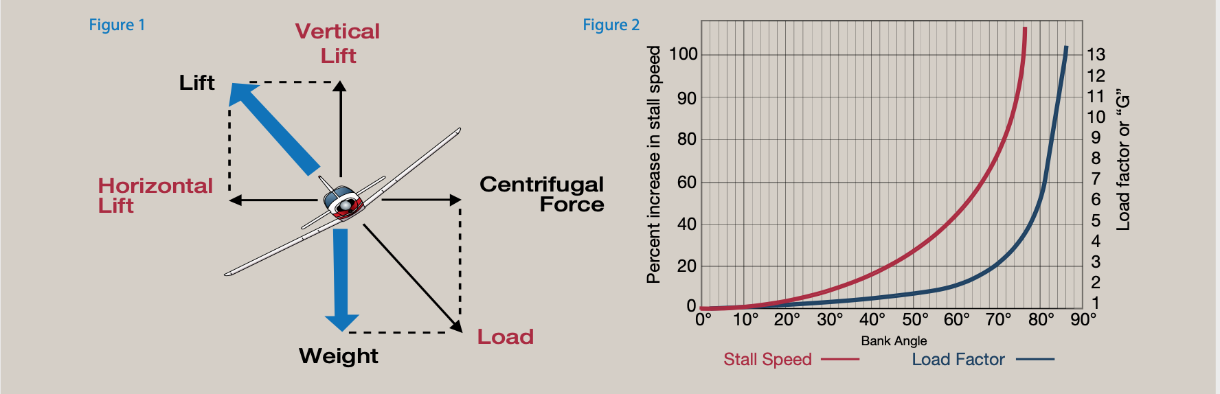
Load Factor Of An Aircraft - Imagine that you are flying s/l and –for some strange reason– the intensity of the earth's gravitational field, (usually expressed as the acceleration of gravity, g) suddenly becomes 3g. In order to keep flying straight and level, you will have to increase your airspeed, or to (prudently) increase the AoA of the wings. Under those conditions, your wings will be stressed to 3g. The 'load factor' will rise to 3g.
During the landing shock, we are allowed to account for an amount of lift from the wings (rotor) since the aircraft is at a speed just below stall and high angle of attack (nose up). The lift coefficient for the stalled wing is usually taken to be from 0.4 to 0.5. If we express the wing lift as a lift factor, P equal to the wing lift divided by the aircraft landing weight, Wt, then the lift during landing is,
Load Factor Of An Aircraft
To address the unnecessarily complicating issue of gravity, you must understand that considering gravity is only necessary to determine the motion or flight path because an aircraft in flight is moving in an accelerated frame of reference. It would be exactly the same as if your aircraft was in an enormous closed box, filled with air, in outer space, under acceleration from a giant rocket strapped on one side, that accelerated the entire box at 32.2 ft/sec2.
Landing Gear Loads
The 14 Code of Federal Regulation (CFR) Part 23 states that the limit inertia load factor for the design of aircraft landing gears must be determined by a drop test or by some rational means. Since a drop test is not possible during the design phase we must look to a rational means to design the landing gears. This analysis is that means.
I = t3 w/12 = 13 6/12 = 0.5 in.4 and for aluminum the modulus of elasticity is, E = 10 106 psi z = 25 inches and let R = 1 lb, then from eq. 12 y = 1 x 253/(3 10 x 106 x 0.5) = 0.00104 in. kleg = 1/y = 961 lb/in. = 11,538 lb/ft.
For fixed wing aircraft weighing less than 12,600 lbs, Part 23 also states that when Wt/S is equal to or smaller than 6.4 psf, Vs is equal to and cannot be smaller than 7 fps. However, gyroplanes have extremely low disc loadings and land softly at low Vs. I therefor propose that we use equation 1 to determine Vs. The free fall height, h, in inches to obtain Vs are given in equation 2.

You only have access to basic statistics. This statistic is not included in your account.
Load factor is simply Aerodynamic Lift divided by aircraft weight, or more correctly, by aircraft inertial mass as normalized by 1 "G" - (32.2 ft/sec2 or 9.98 m/sec2. - CORRECTION (thx to @Michael Kjorling : 9.80665 m/sec2)
And now to the force and moment balance analysis issue, I noticed that all components of an aircraft are expressed in terms of its load factor, which is fine, but then in performing the balance, the weight of the components are not considered. How can you ignore the weight force which is always acting on the aircraft when the load factor (per definition) excludes it? An added confusion is in that lift is considered in the moment balance, with all component's loading expressed in terms of load factor; how can you include lift, when it is already incorporated into the load factor of the components; this implies that the part is further loaded above its current loading.
As we all know, the intensity of the gravitational field is quite stable, and you'll never find yourself flying in the conditions mentioned above, but if your plane follows a curved trajectory, the apparent weight of your plane will be increased by the said inertial forces. If the acceleration (normal to the relative wind) associated with those inertial forces is, for instance, 2g, your wings will be stressed by the load due to gravity plus 2g...
To solve for X, the only unknown in equation 11 is the spring constant K for the landing gear. K is made up of two spring constants. One is the deflection of the tire under load and the other is the deflection of the gear leg or strut.
According to Paragraph 23.473 (d) of Part 23, the velocity Vs depends on the wing loading which we will term the rotor disc loading, Wt/S for the gyroplane at landing weight as shown in equation 1.
For a wing lift coefficient of 0.4 to 0.5, it can be shown that P = 0.667, However for a non feathering rotor that cannot stall, the rotor lift during landing is almost equal to the flight lift and the value of P is set equal to 1. The potential energy, P.E., during the landing gear stroke, X, is,
The load factor of an aircraft describes the mass loading of an aircraft as a multiple of its weight. The same definition applies if we are speaking about an aircraft component: the load factor, here called the local load factor, will be the mass loading of that component as a multiple of that component's weight.
The load factor is the total acceleration you feel, pointing downwards. In straight and level flight, the load factor is 1: you only feel the acceleration of gravity. So a load factor 1 equates to 9.81 m/s$^2$ (If gravity was higher, let's say 15 m/s$^2$. load factor 1 would equate to 15 m/s$^2$. But that's another story.)
First we must understand what mass loading is. The mass load of an aircraft is the inertial loads, as a result of the acceleration of the aircraft and the weight of the aircraft, as a result of the acceleration of gravity. Since the inertial loads always act opposite to the aircraft's acceleration, it is vectorially signed negative. Gravity, as it always points downwards, is in sync with our coordinate system which defines the downward direction as positive; hence, it will be vectorially signed positive. Summing the two vectors will give us the total mass loading of the aircraft. Dividing this total loading by the aircraft's own weight will give us an idea as to how much more that its own weight is the aircraft is currently being loaded by the maneuver it is performing, and by that, how structurally strong it is or needs to be.

U.S. Bureau of Transportation Statistics, Load Factor for U.S. Air Carrier Domestic and International, Scheduled Passenger Flights [LOADFACTOR], retrieved from FRED, Federal Reserve Bank of St. Louis; https://fred.stlouisfed.org/series/LOADFACTOR, March 2, 2023.
Now, however, there is also a sentence in my script that states that the load factor is a means of including all inertial loads and gravity loads in observing the loading of an aircraft; this implies that weight is included in observing the loading of an aircraft: this makes better sense to me, since, when expressing the loading of an aircraft, it would be easier to say that the aircraft is now being loaded "this many times its weight", compared to this many newtons; this however, contradicts the definitions above.
I performed tests on a 6.00 x 6 tire with different tire pressures as shown in figure 3 with the results plotted in table 1. For a tire pressure of 40 psi a maximum tire deflection of 3.6 inches is realized when the tire is loaded to 5,500 lbs. The tire spring constant, ktire is 5,500/3.6 = 1,528 lb/in = 18,333 lb/ft.
To my knowledge, the calculation of landing gear loads for gyroplanes has never been documented. My following article is based on my calculations of landing gear loads for fixed wing aircraft and the Code of Federal Regulations (CRF) Part 23.
To hold a constant "altitude" in the accelerated frame of reference of this giant box, you would have to trim the aircraft so that the wings were producing lift equal to the "weight" (mass x 32.2ft/sec2) of the aircraft. The Lift on the wings (if it equals the weight, just produces an "upwards" acceleration of 32 ft/sec2, which matches the 32.2ft/sec2 that the box is accelerating, and keeps the aircraft the same distance above the "floor" of the box.

Data from all U.S. air carrier domestic and international, scheduled passenger flights. International data in system total includes U.S. carrier operations to and from the U.S. and from one foreign point to another foreign point. BTS’ Airlines and Airports available here does not include U.S. carriers’ foreign point-to-point flights.This data is collected by the U.S. Department of Transportation, Bureau of Transportation Statistics (BTS), U.S. Air Carrier Traffic Statistics reported in BTS' monthly Air Traffic Data release, available here.
The definition given in my university script states that the load factor equals the ratio of all external forces acting on an aircraft minus its weight, to the magnitude of the aircraft's weight; this implies that the load factor is the ratio of all aerodynamic forces acting on an aircraft to the magnitude of its weight.
This equation is accurate since the tire, as seen in figure 3, and the spring gear leg has a linear spring constant. If an oleo strut is used for the landing gear leg, the reaction force, R, of the landing gear is constant such that,
The landing gear of the Sportster was designed to 3.0 gs and many hard landings in a period of 29 years have proven that this load factor is adequate. No landing gear or other structural failures have ever occurred in the Sportster over this time period. The landing gear for the Bumble Bee are designed to 2.5 gs. It should be noted that ng must be multiplied by a safety factor of 1.5 for ultimate (failure) load.
I also need to point out that if the gyroplane has been built, it is easy to determine the landing gear stiffness, K, from weight and balance data and a simple wheel deflection test. Let us say that the load on each main wheel is Wm pounds. With the gyroplane empty, the weight on the main wheels is known. The distance of the fuselage above the ground is measured. With a hoist connected to the airframe, the gyroplane is lift so that the wheels just touch the ground and the new distance of the height of the fuselage off the ground is measured. The difference between the readings is u feet. K is now simply,

Part 23 allows the landing weight, Wt to equal 0.95 x gross weight. For a gross weight of 1,232 lbs the landing weight is 1,170 lbs. The gyroplane has a disc diameter of 30 ft and hence a disc area of p r2 = 3.141 x 152 = 707 sq.ft. so that Wt/S = 1.74 lb/sq.ft. Vs is determined from equation 1 as, Vs= 5 fps. From equation 2, we have a drop height of 4.7 inches. Substituting into equation 10, gives a gear deflection of,
After going through the above calculations, we realize that for the calculations of many iterations in which we try to optimize lets say the tire pressure or landing gear design, it would be best to use a computer program. Such a program is written in BASIC as shown in the next pages. The relation between the gear load, ng, and the aircraft load, n, with P=1.0 is shown in Figure 4.
The units are dimensionless (if both Lift and weight are measured in the same units), but we commonly refer to the load factors in "G"s. It really doesn't matter what the angle of bank is. Even if you are upside down, if the wings are producing twice as much lift as the aircraft weighs, you have 2G's Load factor.
Show sources information Show publisher information Use Ask Statista Research Service
Bank the aircraft 60° and fly a co-ordinated turn, and you'll experience a downward acceleration of 2g. This is a case that is easy to understand since it is a static situation with constant velocities. If we have a dynamic sine wave for instance, the load factor would be a function of where we are in the cycle, if the aircraft is accelerating up or down. The actual acceleration is added to the gravity vector.
The main landing gears on a gyroplane may be viewed by looking at the aircraft from the front as shown in figure 1. The shock absorption of the landing shock occurs just as the tires touch the ground and continues as the tire and landing gear leg deflect and absorb the energy of the vertical sink velocity, Vs, of the landing gyroplane. A simplified view of the two conditions of landing are shown in figure 2. Each condition in figure 2 is the same view as figure 1 but the landing gear and tires have been represented by a single spring with a spring constant of K in lb/inch or in lb/feet. To convert simply multiply lb/in. by 12 to get lb/ft.
Knowing the load factor alone does not tell us how much stress is being exerted on, say, the connection between the wing and the fuselage. This will be affected by how the mass of the aircraft is distributed. It also will be affected by whether or not the horizontal tail is generating a downward lift force, which requires the wing to generate more lift to achieve a given Load Factor. For more on this see this answer to the related question "How does an aircraft's weight affect the V-n diagram?" How does an aircraft's weight affect the V-n diagram?
aircraft load factor formula, inertial loads on aircraft, aircraft load factor chart, load factor aeronautics, load factor chart, ultimate load factor aircraft, flight load factor, airline load factor formula