Wednesday, March 1, 2023

Long Beach Aircraft Carrier

Long Beach Aircraft Carrier

Long Beach Aircraft Carrier - An Essex-class aircraft carrier, USS Shangri-La (CV-38) entered service in 1944. One of over 20 Essex-class carriers built for the US Navy during World War II, it joined the US Pacific Fleet and supported Allied operations during the final phases of the island-hopping campaign across the Pacific. Modernized in the 1950s, Shangri-La later served extensively in the Atlantic and Mediterranean before taking part in the Vietnam War.  Completing its time off Southeast Asia, the carrier was decommissioned in 1971.

He checked aboard the Kitty Hawk shortly after an engine room fire took the lives of five sailors. The inferno injured at least three dozen others, according to the Naval History and Heritage Command. Shaw said connecting to other R-Division veterans, who were the ship’s primary firefighters, through the Facebook group made him appreciate what those sailors endured in the wake of the tragedy.

Long Beach Aircraft Carrier

What's In Store For Southwest, Now The Top Carrier At Lgb • Long Beach  Business Journal

“Ships are haunted — they hold the soul of the crew,” he said. “The attachment of a ship and a crew maybe transcends rational thought. You invest your energy, your emotion, your friends, your dead friends ... how many hugely emotional events in a sailor’s life are associated with the crew, with the Kitty Hawk?”

‘Geriatrics For Carriers’

Returning to Ulithi, the carrier embarked Vice Admiral John S. McCain, Sr. in late May when he relieved Mitscher.  Becoming flagship of the task force, Shangri-La led the American carriers north in early June and began a series of raids against the Japanese home islands. The next several days saw Shangri-La evade a typhoon while shuttling between strikes on Okinawa and Japan. On June 13, the carrier departed for Leyte where it spent the remainder of the month engaged in maintenance. Resuming combat operations on July 1, Shangri-La returned to Japanese waters and began a series of attacks across the length of the country.

“This was my first ship and there’s a lot of memories,” he said. “In ‘81, just after pulling out of port, I got to hunt my first Russian submarine. I’ve been on several ships and the Kitty Hawk is one of the most memorable.”

Although not the first so-called “supercarrier,” the Kitty Hawk was hailed at the time as the “forerunner of a new and greatly improved line of carriers,” by Adm. Arleigh Burke, then the chief of naval operations.

The most noticeable of these changes was lengthening the bow to a clipper design which permitted the installation of two quadruple 40 mm mounts. Other alterations included moving the combat information center under the armored deck, enhanced ventilation and aviation fuel systems, a second catapult on the flight deck, and an additional fire control director. Referred to as the "long-hull" Essex-class or Ticonderoga-class by some, the US Navy made no distinction between these and the earlier Essex-class ships.

George H.w. Bush Carrier Strike Group Departs Norfolk | 13Newsnow.com

Ship History

While operating in the Atlantic in October 1965, Shangri-La was accidentally rammed by the destroyer USS Newman K. Perry. Though the carrier was not badly damaged, the destroyer suffered one fatality.  Re-designated an anti-submarine carrier (CVS-38) on June 30, 1969, Shangri-La received orders early the following year to join the US Navy's efforts during the Vietnam War. Sailing via the Indian Ocean, the carrier reached the Philippines on April 4, 1970. Operating from Yankee Station, Shangri-La's aircraft commenced combat missions over Southeast Asia. Remaining active in the region for the next seven months, it then departed for Mayport via Australia, New Zealand, and Brazil.

“Ships are haunted — they hold the soul of the crew. The attachment of a ship and a crew maybe transcends rational thought. You invest your energy, your emotion, your friends, your dead friends ... how many hugely emotional events in a sailor’s life are associated with the crew, with the Kitty Hawk?”

Transferred to the Atlantic in 1960, Shangri-La participated in NATO exercises as well as moved to the Caribbean in response to troubles in Guatemala and Nicaragua. Based at Mayport, FL, the carrier spent the next nine years operating in the western Atlantic and Mediterranean. Following a deployment with the US Sixth Fleet in 1962, Shangri-La underwent an overhaul at New York which saw installation of new arrestor gear and radar systems as well as removal of four 5" gun mounts.

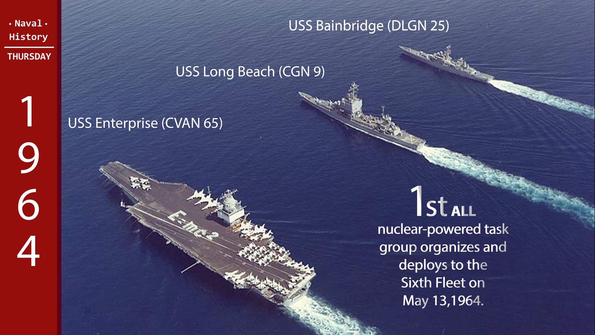
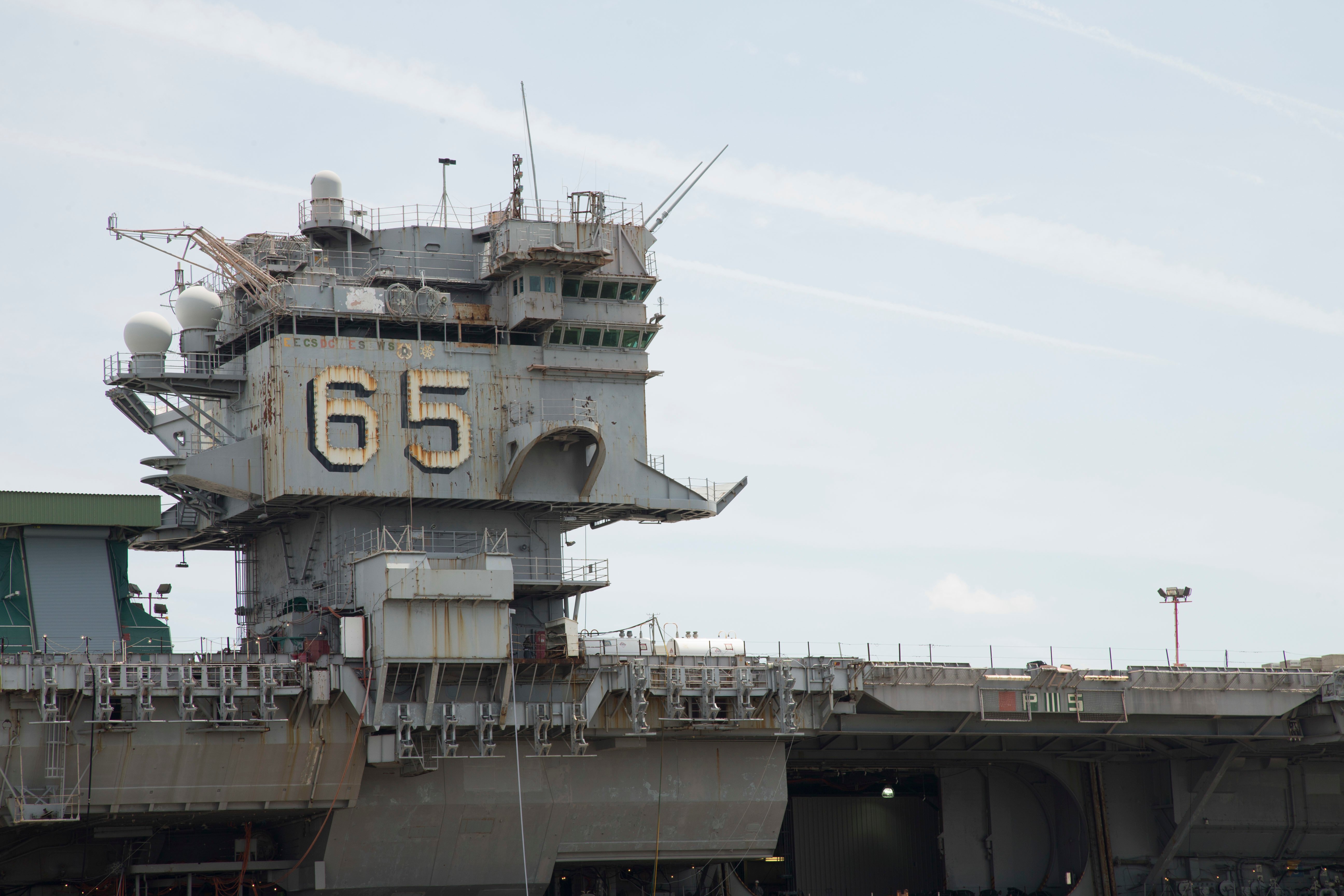
The world's first nuclear-powered aircraft carrier was commissioned on 25 November 1961 and completed 25 deployments during 51 years of service. Click the links below to access the Dictionary of American Naval Fighting Ships entries for Enterprise, which provide the carrier's history by time period.

Cold War

The Kitty Hawk was the next-to-last U.S. aircraft carrier built to run on diesel fuel. The nuclear-powered Enterprise was launched the same year and the Nimitz was commissioned in 1975, launching a new class of 10 reactor-fueled carriers. Two of them, the Abraham Lincoln and the Carl Vinson, are currently based in San Diego.

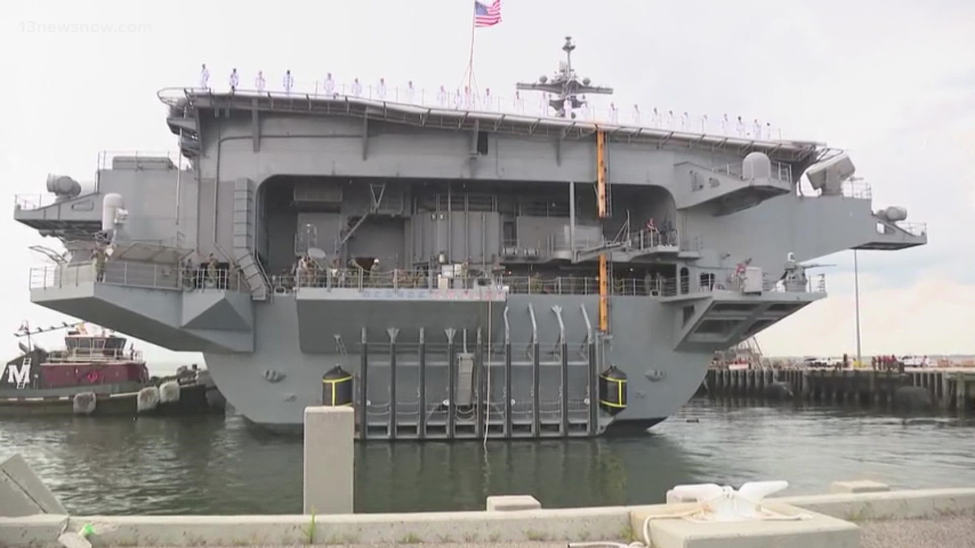
The Kitty Hawk would call San Diego home for the next 37 years, before spending its last decade of operations in Japan. It was decommissioned in 2009. For the next 12 years, it would sit with other retired ships in Puget Sound, Wash.

Dvids - Images - May 13Th Today's Day In History - First Nuclear-Powered  Task Group

All of the sailors who spoke with the Union-Tribune about the Kitty Hawk said they believed it held a unique place in the Navy compared with other ships that have been lost to the scrapyard. Maybe it has something to do with the sheer number of lives touched by the ship over nearly a half century, directly or through the family and friends of those who served on board.

I’m one of them; I served on the ship as an aviation electronics technician from January 2003 to January 2007, when it was based in Japan. We were always busy and always out to sea and the shared suffering forged lasting friendships among the crew.

A New Design

The first ship to undergo the SCB-125 upgrade, Shangri-La was the second American carrier to possess an angled flight deck after USS Antietam (CV-36). Completed in January 1955, the carrier rejoined the fleet and spent much of the year engaged in training before deploying to the Far East in early 1956. The next four years were spent alternating between San Diego and Asian waters.

Designed in the 1920s and 1930s, the US Navy's Lexington- and Yorktown-class aircraft carriers were intended to meet the limitations set forth by the Washington Naval Treaty. This levied restrictions on the tonnage of different types of warships as well as placed a ceiling on each signatory’s total tonnage. This system was further revised and extended by the 1930 London Naval Treaty. As the international situation deteriorated in the 1930s, Japan and Italy elected to depart the treaty structure.

Jason Chudy, a retired Navy chief living near Seattle, estimates that about 250,000 sailors served on the carrier during its lifespan. Chudy is the membership coordinator for the Kitty Hawk Veteran’s Association, and he was involved in the effort to save the ship from the scrapper.

As is often the case, the men — and, starting in 1994, women — who served on the Kitty Hawk through the years came to see it as home, and many harbored deep attachments long after their service.

Navy May Dismantle Former Nuclear-Powered Aircraft Carrier Enterprise At  Commercial Yard - Usni News

Cat And Mouse

Arriving home on December 16, 1970, Shangri-La began preparations for inactivation. These were completed at the Boston Naval Shipyard. Decommissioned on July 30, 1971, the carrier moved to the Atlantic Reserve Fleet at the Philadelphia Naval Shipyard. Stricken from the Naval Vessel Register on July 15, 1982, the ship was retained to provide parts for USS Lexington (CV-16).  On August 9, 1988, Shangri-La was sold for scrap.

In November 1952, the carrier arrived at Puget Sound Naval Shipyard for a major overhaul. This saw Shangri-La receive both SCB-27C and SCB-125 upgrades. While the former included major alteration's to the carrier's island, relocation of several facilities within the ship, and the addition of steam catapults, the later saw the installation of an angled flight deck, an enclosed hurricane bow, and a mirror landing system.

The aircraft carrier Kitty Hawk steamed into San Diego in the fall of 1961 with fanfare usually enjoyed by royalty, wrote the San Diego Union’s Lester Bell in a story announcing the warship’s arrival. A swing band on a barge at the mouth of the newly-dredged harbor channel played “California Here I Come,” and fire boats spraying plumes of water escorted it to North Island.

“I’m disappointed San Diego and the Navy aren’t doing something to recognize the Kitty Hawk passing by one last time,” Shaw said. “It’s awesome to be in touch with (other veterans) and know that their time on the Kitty Hawk was meaningful and that we have something in common.”

The Standard Design

The Kitty Hawk’s keel was laid Dec. 27, 1956, at New York Shipbuilding in Camden, N.J. at a final cost of $178 million, or $1.7 billion in 2022 dollars. (Compare that with the $13 billion cost of the Navy’s latest carrier, the nuclear powered Gerald R. Ford.)

“My chief engineer told me once the steam plant on the Kitty Hawk is the most complicated machine ever built or maintained by human beings,” Parker said. “We had a problem finding engineers and were calling people back to active duty to help man the ship. We called it ‘geriatrics for aircraft carriers.’”

Retired Aircraft Carrier Kitty Hawk Makes California Stop | Kmph

The first ship to move forward with the altered Essex-class design was USS Hancock (CV-14) which was later re-named Ticonderoga. This was followed by additional ships including USS Shangri-La (CV-38).  Construction commenced January 15, 1943, at the Norfolk Naval Shipyard. A significant departure from US Navy naming conventions, Shangri-La referenced a distant land in James Hilton's Lost Horizons.

The Kitty Hawk’s 48 years of service life spanned 10 presidents and several overseas conflicts. The ship deployed multiple times to Vietnam, fought in the Gulf War and during the War on Terror in Afghanistan and Iraq.

World War Ii

Stephen Sherman, another San Diego Kitty Hawk veteran, worked in the Crash and Salvage division on the ship’s flight deck, the first responders for aircraft fires. On July 11, 1994, an F-14 Tomcat crashed onto the ship’s pitching flight deck, broke in two, and exploded into a fireball.

Shaw was the Repair Division officer from 1974 to 1975. He only spent four years in the Navy. He said he had a low draft number, which pushed him to volunteer for the sea service rather than risk being sent to the jungles of Vietnam.

Construction commenced on the lead ship, USS Essex (CV-9), on April 28, 1941. With the US entry into World War II following the attack on Pearl Harbor, the Essex-class soon became the US Navy's principal design for fleet carriers. The first four vessels after Essex followed the class' initial design. In early 1943, the US Navy requested several changes to improve future vessels.

The two aviators on the jet ejected and landed on the flight deck — one of them in the burning wreckage of the jet. Sherman’s team jumped into action. He manned a fire hose while his fellow sailors pulled the man out of the wreckage. Although he suffered burns, he eventually recovered, Sherman said.

Us Carrier Arrives At Scrapyard After One-Cent Dismantling Deal

Postwar Years

The name was chosen as President Franklin D. Roosevelt had cheekily stated that the bombers used in the 1942 Doolittle Raid had departed from a base in Shangri-La.  Entering the water on February 24, 1944, Josephine Doolittle, wife of Major General Jimmy Doolittle, served as sponsor. Work quickly advanced and Shangri-La entered commission on September 15, 1944, with Captain James D. Barner in command.

So it was that on Jan. 15 the Kitty Hawk was tugged out of Bremerton, Wash., for a slow tow around Cape Horn, Chile, en route to its final, ignominious end: a Brownsville, Texas ship breaker. Its 60,000 tons of steel will be sold off as scrap.

Despite those challenges, the ship was instrumental in the U.S. military response after the attacks of Sept. 11, 2001. The Kitty Hawk, based in Japan, was the first carrier to deploy in support of Operation Enduring Freedom. By mid-October, the ship was in the Persian Gulf operating as a staging base for Army Special Forces. It would again deploy to the Gulf in February 2003 and launched some of the first sorties against Iraq that March.

Completing shakedown operations later that fall, Shangri-La departed Norfolk for the Pacific in January 1945 in company with the heavy cruiser USS Guam and the destroyer USS Harry E. Hubbard.. After touching at San Diego, the carrier proceeded to Pearl Harbor where it spent two months engaged in training activities and carrier-qualifying pilots. In April, Shangri-La left Hawaiian waters and steamed for Ulithi with orders to join Vice Admiral Marc A. Mitscher's Task Force 58 (Fast Carrier Task Force).  Rendezvousing with TF 58, the carrier launched its first strike the next day when its aircraft attacked Okino Daito Jima. Moving north Shangri-La then began supporting Allied efforts during the Battle of Okinawa.

One Last Look?

beach aircraft sales, best beach carrier, r&l carriers long beach, beach baby carrier

Load Factor Of An Aircraft

Load Factor Of An Aircraft

Load Factor Of An Aircraft - Imagine that you are flying s/l and –for some strange reason– the intensity of the earth's gravitational field, (usually expressed as the acceleration of gravity, g) suddenly becomes 3g. In order to keep flying straight and level, you will have to increase your airspeed, or to (prudently) increase the AoA of the wings. Under those conditions, your wings will be stressed to 3g. The 'load factor' will rise to 3g.

During the landing shock, we are allowed to account for an amount of lift from the wings (rotor) since the aircraft is at a speed just below stall and high angle of attack (nose up). The lift coefficient for the stalled wing is usually taken to be from 0.4 to 0.5. If we express the wing lift as a lift factor, P equal to the wing lift divided by the aircraft landing weight, Wt, then the lift during landing is,

Load Factor Of An Aircraft

Aerospace | Free Full-Text | Flight Load Assessment For Light Aircraft  Landing Trajectories In Windy Atmosphere And Near Wind Farms

To address the unnecessarily complicating issue of gravity, you must understand that considering gravity is only necessary to determine the motion or flight path because an aircraft in flight is moving in an accelerated frame of reference. It would be exactly the same as if your aircraft was in an enormous closed box, filled with air, in outer space, under acceleration from a giant rocket strapped on one side, that accelerated the entire box at 32.2 ft/sec2.

Landing Gear Loads

The 14 Code of Federal Regulation (CFR) Part 23 states that the limit inertia load factor for the design of aircraft landing gears must be determined by a drop test or by some rational means. Since a drop test is not possible during the design phase we must look to a rational means to design the landing gears. This analysis is that means.

I = t3 w/12 = 13 6/12 = 0.5 in.4 and for aluminum the modulus of elasticity is, E = 10 106 psi z = 25 inches and let R = 1 lb, then from eq. 12 y = 1 x 253/(3 10 x 106 x 0.5) = 0.00104 in. kleg = 1/y = 961 lb/in. = 11,538 lb/ft.

For fixed wing aircraft weighing less than 12,600 lbs, Part 23 also states that when Wt/S is equal to or smaller than 6.4 psf, Vs is equal to and cannot be smaller than 7 fps. However, gyroplanes have extremely low disc loadings and land softly at low Vs. I therefor propose that we use equation 1 to determine Vs. The free fall height, h, in inches to obtain Vs are given in equation 2.

Ecfr :: 14 Cfr Part 25 Subpart C - Flight Maneuver And Gust Conditions (Far  Part 25 Subpart C - Ecfr3e855ea22ea15d0)

You only have access to basic statistics. This statistic is not included in your account.

Load factor is simply Aerodynamic Lift divided by aircraft weight, or more correctly, by aircraft inertial mass as normalized by 1 "G" - (32.2 ft/sec2 or 9.98 m/sec2. - CORRECTION (thx to @Michael Kjorling : 9.80665 m/sec2)

And now to the force and moment balance analysis issue, I noticed that all components of an aircraft are expressed in terms of its load factor, which is fine, but then in performing the balance, the weight of the components are not considered. How can you ignore the weight force which is always acting on the aircraft when the load factor (per definition) excludes it? An added confusion is in that lift is considered in the moment balance, with all component's loading expressed in terms of load factor; how can you include lift, when it is already incorporated into the load factor of the components; this implies that the part is further loaded above its current loading.

As we all know, the intensity of the gravitational field is quite stable, and you'll never find yourself flying in the conditions mentioned above, but if your plane follows a curved trajectory, the apparent weight of your plane will be increased by the said inertial forces. If the acceleration (normal to the relative wind) associated with those inertial forces is, for instance, 2g, your wings will be stressed by the load due to gravity plus 2g...

To solve for X, the only unknown in equation 11 is the spring constant K for the landing gear. K is made up of two spring constants. One is the deflection of the tire under load and the other is the deflection of the gear leg or strut.

Steep Turns - Aviation Safety

According to Paragraph 23.473 (d) of Part 23, the velocity Vs depends on the wing loading which we will term the rotor disc loading, Wt/S for the gyroplane at landing weight as shown in equation 1.

For a wing lift coefficient of 0.4 to 0.5, it can be shown that P = 0.667, However for a non feathering rotor that cannot stall, the rotor lift during landing is almost equal to the flight lift and the value of P is set equal to 1. The potential energy, P.E., during the landing gear stroke, X, is,

The load factor of an aircraft describes the mass loading of an aircraft as a multiple of its weight. The same definition applies if we are speaking about an aircraft component: the load factor, here called the local load factor, will be the mass loading of that component as a multiple of that component's weight.

The load factor is the total acceleration you feel, pointing downwards. In straight and level flight, the load factor is 1: you only feel the acceleration of gravity. So a load factor 1 equates to 9.81 m/s$^2$ (If gravity was higher, let's say 15 m/s$^2$. load factor 1 would equate to 15 m/s$^2$. But that's another story.)

First we must understand what mass loading is. The mass load of an aircraft is the inertial loads, as a result of the acceleration of the aircraft and the weight of the aircraft, as a result of the acceleration of gravity. Since the inertial loads always act opposite to the aircraft's acceleration, it is vectorially signed negative. Gravity, as it always points downwards, is in sync with our coordinate system which defines the downward direction as positive; hence, it will be vectorially signed positive. Summing the two vectors will give us the total mass loading of the aircraft. Dividing this total loading by the aircraft's own weight will give us an idea as to how much more that its own weight is the aircraft is currently being loaded by the maneuver it is performing, and by that, how structurally strong it is or needs to be.

What Is An Airline's Load Factor And Why Does It Matter?

U.S. Bureau of Transportation Statistics, Load Factor for U.S. Air Carrier Domestic and International, Scheduled Passenger Flights [LOADFACTOR], retrieved from FRED, Federal Reserve Bank of St. Louis; https://fred.stlouisfed.org/series/LOADFACTOR, March 2, 2023.

Now, however, there is also a sentence in my script that states that the load factor is a means of including all inertial loads and gravity loads in observing the loading of an aircraft; this implies that weight is included in observing the loading of an aircraft: this makes better sense to me, since, when expressing the loading of an aircraft, it would be easier to say that the aircraft is now being loaded "this many times its weight", compared to this many newtons; this however, contradicts the definitions above.

I performed tests on a 6.00 x 6 tire with different tire pressures as shown in figure 3 with the results plotted in table 1. For a tire pressure of 40 psi a maximum tire deflection of 3.6 inches is realized when the tire is loaded to 5,500 lbs. The tire spring constant, ktire is 5,500/3.6 = 1,528 lb/in = 18,333 lb/ft.

To my knowledge, the calculation of landing gear loads for gyroplanes has never been documented. My following article is based on my calculations of landing gear loads for fixed wing aircraft and the Code of Federal Regulations (CRF) Part 23.

To hold a constant "altitude" in the accelerated frame of reference of this giant box, you would have to trim the aircraft so that the wings were producing lift equal to the "weight" (mass x 32.2ft/sec2) of the aircraft. The Lift on the wings (if it equals the weight, just produces an "upwards" acceleration of 32 ft/sec2, which matches the 32.2ft/sec2 that the box is accelerating, and keeps the aircraft the same distance above the "floor" of the box.

Maneuvering Speed - Wikipedia

Data from all U.S. air carrier domestic and international, scheduled passenger flights. International data in system total includes U.S. carrier operations to and from the U.S. and from one foreign point to another foreign point. BTS’ Airlines and Airports available here does not include U.S. carriers’ foreign point-to-point flights.This data is collected by the U.S. Department of Transportation, Bureau of Transportation Statistics (BTS), U.S. Air Carrier Traffic Statistics reported in BTS' monthly Air Traffic Data release, available here.

The definition given in my university script states that the load factor equals the ratio of all external forces acting on an aircraft minus its weight, to the magnitude of the aircraft's weight; this implies that the load factor is the ratio of all aerodynamic forces acting on an aircraft to the magnitude of its weight.

This equation is accurate since the tire, as seen in figure 3, and the spring gear leg has a linear spring constant. If an oleo strut is used for the landing gear leg, the reaction force, R, of the landing gear is constant such that,

The landing gear of the Sportster was designed to 3.0 gs and many hard landings in a period of 29 years have proven that this load factor is adequate. No landing gear or other structural failures have ever occurred in the Sportster over this time period. The landing gear for the Bumble Bee are designed to 2.5 gs. It should be noted that ng must be multiplied by a safety factor of 1.5 for ultimate (failure) load.

I also need to point out that if the gyroplane has been built, it is easy to determine the landing gear stiffness, K, from weight and balance data and a simple wheel deflection test. Let us say that the load on each main wheel is Wm pounds. With the gyroplane empty, the weight on the main wheels is known. The distance of the fuselage above the ground is measured. With a hoist connected to the airframe, the gyroplane is lift so that the wheels just touch the ground and the new distance of the height of the fuselage off the ground is measured. The difference between the readings is u feet. K is now simply,

Why Does Stall Speed Increase With Bank Angle? | Boldmethod

Part 23 allows the landing weight, Wt to equal 0.95 x gross weight. For a gross weight of 1,232 lbs the landing weight is 1,170 lbs. The gyroplane has a disc diameter of 30 ft and hence a disc area of p r2 = 3.141 x 152 = 707 sq.ft. so that Wt/S = 1.74 lb/sq.ft. Vs is determined from equation 1 as, Vs= 5 fps. From equation 2, we have a drop height of 4.7 inches. Substituting into equation 10, gives a gear deflection of,

After going through the above calculations, we realize that for the calculations of many iterations in which we try to optimize lets say the tire pressure or landing gear design, it would be best to use a computer program. Such a program is written in BASIC as shown in the next pages. The relation between the gear load, ng, and the aircraft load, n, with P=1.0 is shown in Figure 4.

The units are dimensionless (if both Lift and weight are measured in the same units), but we commonly refer to the load factors in "G"s. It really doesn't matter what the angle of bank is. Even if you are upside down, if the wings are producing twice as much lift as the aircraft weighs, you have 2G's Load factor.

Show sources information Show publisher information Use Ask Statista Research Service

Bank the aircraft 60° and fly a co-ordinated turn, and you'll experience a downward acceleration of 2g. This is a case that is easy to understand since it is a static situation with constant velocities. If we have a dynamic sine wave for instance, the load factor would be a function of where we are in the cycle, if the aircraft is accelerating up or down. The actual acceleration is added to the gravity vector.

The main landing gears on a gyroplane may be viewed by looking at the aircraft from the front as shown in figure 1. The shock absorption of the landing shock occurs just as the tires touch the ground and continues as the tire and landing gear leg deflect and absorb the energy of the vertical sink velocity, Vs, of the landing gyroplane. A simplified view of the two conditions of landing are shown in figure 2. Each condition in figure 2 is the same view as figure 1 but the landing gear and tires have been represented by a single spring with a spring constant of K in lb/inch or in lb/feet. To convert simply multiply lb/in. by 12 to get lb/ft.

Knowing the load factor alone does not tell us how much stress is being exerted on, say, the connection between the wing and the fuselage. This will be affected by how the mass of the aircraft is distributed. It also will be affected by whether or not the horizontal tail is generating a downward lift force, which requires the wing to generate more lift to achieve a given Load Factor. For more on this see this answer to the related question "How does an aircraft's weight affect the V-n diagram?" How does an aircraft's weight affect the V-n diagram?

aircraft load factor formula, inertial loads on aircraft, aircraft load factor chart, load factor aeronautics, load factor chart, ultimate load factor aircraft, flight load factor, airline load factor formula

Lodestar Aircraft

Lodestar Aircraft

Lodestar Aircraft - We've toured "Goodtime Gal" and highly recommend a visit to see this expertly restored aircraft. For more information and for the aircraft's tour schedule, please visit the website of the Houston Wing of the Commemorative Air Force.

– XR5O-1- powered by Wright R-1820-40 engines with 895 kW. 1 example built, – R5O-1- powered by Wright R-1820-97 engines with 895 kW. 3 examples were built, one was transferred to United States Coast Guard, – R5O-2- powered by Pratt & Whitney R-1690-25 engines with power 634 kW.

Lodestar Aircraft

A Quality Freeware On A Par With Payware: The Lockheed Lodestar - Msfs 2020  Users Screenshots - Flightsim.com

1 ex. was built, – R5O-3- powered by Pratt & Whitney R-1830-34A engines with 895 kW. Initially it was a VIP transport aircraft for 4 passengers. There were built 4 examples, – R5O-4- powered by Wright R-1820-40 engines with power 895 kW.

Aircraft Photo Of Zs-Atc |

Versions Built For The Us Navy

It was a staff transport plane for 7 passengers. There were 12 built, – R5O-5- powered by Wright R-1820-40 engines with 895 kW. Similar to R5O-4 but with seats for 14 passengers. 14 examples were built,

– R5O-6- designation of 35 aircraft C-60A-5-LO which were transferred by USAAC to the US Navy (USMC), they took 18 soldiers on board. In 1941-1943 the large-series production of the planes for the transport aviation was started.

Olixsim Lockheed Lodestar Model 18

For USAAF there were built 10 ex. C-59, 30 ex. C-60 (15 of them were given to Great Britain) and 325 C-60A. C-60A. They had simplified equipment of passenger cabin and reinforced floor. The planes were unarmed, in the C-60 and C-60A versions there were openings in the cabin windows for fire from the airborne small arms.

About 100 copies were delivered to the aviation of the United States Navy. In total 625 aircraft of the Lockheed Model 18 family were built. The transport aircrafts of Lockheed Model 18 family were used in the military aviation: Australia, Brazil, Dutch East Indies, Canada, New Zealand, Norway, South Africa, USA, UK.

80-G-K-827 Lockheed R50

C-A Goodtime Gal A Finely Restored Survivor

On the basis of the aircraft Lockheed Model 18 Lodestar there was constructed a maritime patrol aircraft Ventura. The C-60A was the first "Lodestar" which was built specifically for military service. It was used as a cargo aircraft, VIP transport and paratroop transport.

C-60A's also served with the Royal Air Force, Royal Australian Air Force, Royal Canadian Air Force, Royal New Zealand Air Force, South African Air Force and Netherlands East Indies Air Force. In May 1941, the USAAF purchased one L-18-20 (under the designation C-56) and three L-18-14s (as C-57), followed by a further 10 C-57s.

Lockheed C.56/C.60 Lodestar

The C-57 were ordinary passenger aircraft used to transport staff officers. When the USA entered the Second World War, a number of Model 18 aircraft of various versions were purchased for military aviation. In 1941-1943 the large-scale production of aircraft for the transport aviation developed.

The C-60A is a twin-engine transport airplane based on the Lockheed Model 18, a civilian airliner, developed as a competitor to the Douglas DC-3. Slightly smaller and faster than the DC-3, the plane saw service with many airlines around the world.

Lockheed Lodestar

Versions Built For Usaaf

At the beginning of the war, 102 Model 18's were in service with the U.S. airlines or under construction were pressed into military service; These aircraft were designated C-56, C-57, C-59 or C-60 depending on their configuration and engines.

The C-60A "Goodtime Gal" was restored over an 8-year period by the Houston Wing of the Commemorative Air Force, and made its first flight after restoration in August of 2011. The aircraft was built in 1943, and is configured as a

paratroop transport plane, complete with jump lights and a static line hookup. This is the same role in which she served during her military service. ABOUT THIS SITE | TERMS OF USE | PRIVACY POLICY |

CONTACT US Copyright © 2023 Airplanes-Online.com Lockheed also developed the Ventura medium bomber for the British using the same basic airframe. The Ventura was armed with up to eight .303 and two .50 caliber machine guns, and could carry 2,500 pounds of bombs.

Although initially flown in attacks against land targets, it was primarily used as a patrol bomber in an anti-submarine and anti-shipping role.

lockheed lodestar pic, lockheed loadstar world war ii, lockheed lodestar, lodestar plane, lockheed c 60 lodestar, c 60 aircraft, lockheed lodestar aircraft for sale, c 56 aircraft